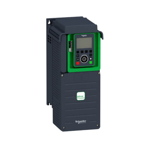
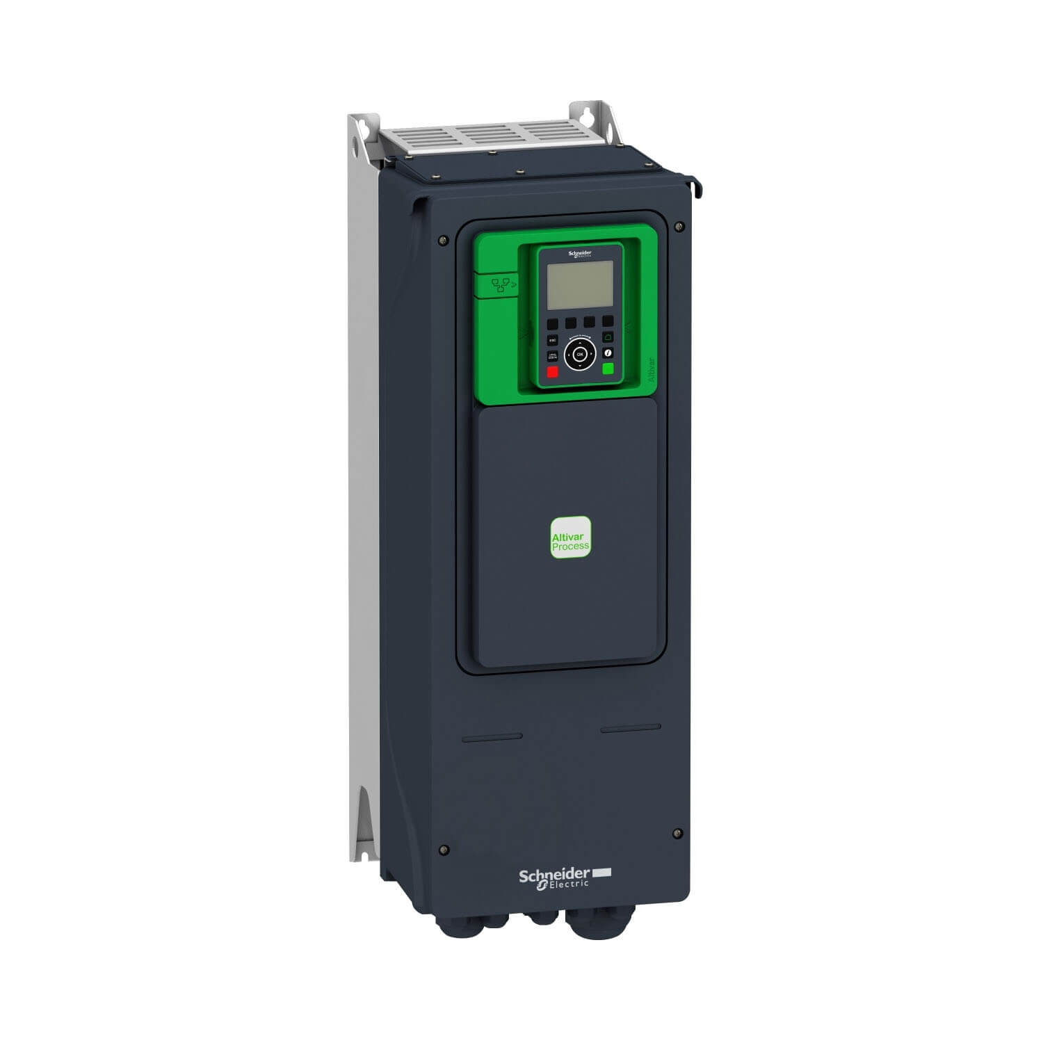
ATV650U22N4 Variable speed drive, ATV650, 2.2 kW, 400…480V, IP55
Specification:
| range of product | Altivar Process ATV600 | |
|---|---|---|
| product or component type | Variable speed drive | |
| product specific application | Process and utilities | |
| device short name | ATV650 | |
| variant | Standard version | |
| product destination | Synchronous motors Synchronous motors | |
| EMC filter | Integrated with 150 m conforming to EN/IEC 61800-3 category C3 Integrated with 50 m conforming to EN/IEC 61800-3 category C2 | |
| IP degree of protection | IP55 conforming to IEC 60529 IP55 conforming to IEC 61800-5-1 | |
| type of cooling | Forced convection | |
| supply frequency | 50…60 Hz – 5…5 % | |
| network number of phases | 3 phases | |
| [Us] rated supply voltage | 380…480 V – 15…10 % | |
| motor power kW | 0.75 kW (heavy duty) 2.2 kW (normal duty) | |
| motor power hp | 1 hp heavy duty 3 hp normal duty | |
| line current | 2.6 A at 480 V (normal duty) 1.7 A at 380 V (heavy duty) 1.5 A at 480 V (heavy duty) 4.3 A at 380 V (normal duty) | |
| prospective line Isc | 50 kA | |
| apparent power | 1.2 kVA at 480 V (heavy duty) 3.2 kVA at 480 V (normal duty) | |
| continuous output current | 2.2 A at 4 kHz for heavy duty 5.6 A at 4 kHz for normal duty | |
| maximum transient current | 3.3 A during 60 s (heavy duty) 6 A during 60 s (heavy duty) | |
| asynchronous motor control profile | Variable torque standard Optimized torque mode Constant torque standard | |
| synchronous motor control profile | Synchronous reluctance motor Permanent magnet motor | |
| Output frequency | 0.0001…0.5 kHz | |
| speed drive output frequency | 0.1…599 Hz | |
| nominal switching frequency | 4 kHz | |
| switching frequency | 4…12 kHz with derating factor 2…12 kHz adjustable | |
| safety function | STO (safe torque off) SIL 3 | |
| discrete input logic | 16 preset speeds | |
| communication port protocol | Modbus serial Ethernet Modbus TCP | |
| option card | Slot A: communication module, Profinet Slot A: communication module, DeviceNet Slot A: communication module, Modbus TCP/EtherNet/IP Slot A: communication module, CANopen daisy chain RJ45 Slot A: communication module, CANopen SUB-D 9 Slot A: communication module, CANopen screw terminals Slot A/slot B: digital and analog I/O extension module Slot A/slot B: output relay extension module Slot A: communication module, Ethernet IP/Modbus TCP/MD-Link Communication module, BACnet MS/TP Communication module, Ethernet Powerlink Slot A: communication module, Profibus DP V1 |
| output voltage | <= power supply voltage | |
|---|---|---|
| permissible temporary current boost | 1.5 x In during 60 s (heavy duty) 1.1 x In during 60 s (normal duty) | |
| motor slip compensation | Can be suppressed Automatic whatever the load Adjustable Automatic whatever the load | |
| acceleration and deceleration ramps | Linear adjustable separately from 0.01…9999 s | |
| braking to standstill | By DC injection | |
| protection type | Safe torque off: motor Motor phase break: motor Thermal protection: drive Safe torque off: drive Overheating: drive Overcurrent between output phases and earth: drive Overload of output voltage: drive Short-circuit protection: drive Motor phase break: drive Overvoltages on the DC bus: drive Line supply overvoltage: drive Line supply undervoltage: drive Line supply phase loss: drive Overspeed: drive Break on the control circuit: drive Thermal protection: motor | |
| frequency resolution | Analog input: 0.012/50 Hz Display unit: 0.1 Hz | |
| electrical connection | Line side: screw terminal4…6 mm²/AWG 12…AWG10 Motor: screw terminal4…6 mm²/AWG 12…AWG10 Control: removable screw terminals0.5…1.5 mm²/AWG 20…AWG 16 | |
| connector type | RJ45 (on the remote graphic terminal) for Modbus serial RJ45 (on the remote graphic terminal) for Ethernet/Modbus TCP | |
| physical interface | 2-wire RS 485 for Modbus serial | |
| transmission frame | RTU for Modbus serial | |
| transmission rate | 4.8, 9.6, 19.2, 38.4 kbit/s for Modbus serial 10/100 Mbit/s for Ethernet IP/Modbus TCP | |
| exchange mode | Half duplex, full duplex, autonegotiation Ethernet/Modbus TCP | |
| data format | 8 bits, configurable odd, even or no parity for Modbus serial | |
| type of polarization | No impedance for Modbus serial | |
| number of addresses | 1…247 for Modbus serial | |
| method of access | Slave Modbus TCP | |
| supply | Internal supply for reference potentiometer (1 to 10 kOhm): 10.5 V DC +/- 5 %, <10 mA, protection type: overload and short-circuit protection Internal supply for digital inputs and STO: 24 V DC (21…27 V), <200 mA, protection type: overload and short-circuit protection External supply for digital inputs: 24 V DC (19…30 V), <1.25 mA, protection type: overload and short-circuit protection | |
| local signalling | 3 LEDs (dual colour) for embedded communication status 4 LEDs (dual colour) for communication module status 1 LED (red) for presence of voltage 3 LEDs for local diagnostic | |
| width | 264 mm | |
| height | 678 mm | |
| depth | 272 mm | |
| net weight | 10.5 kg | |
| analogue input number | 3 | |
| analogue input type | AI1, AI2, AI3 software-configurable current: 0…20 mA/4…20 mA, impedance: 250 Ohm, resolution 12 bits AI1, AI2, AI3 software-configurable voltage: 0…10 V DC, impedance: 30 kOhm, resolution 12 bits | |
| discrete input number | 8 | |
| discrete input type | DI5, DI6 programmable as pulse input: 0…30 kHz, 24 V DC (<= 30 V) STOA, STOB safe torque off, 24 V DC (<= 30 V), impedance: > 2.2 kOhm DI1…DI6 programmable, 24 V DC (<= 30 V), impedance: 3.5 kOhm | |
| input compatibility | DI5, DI6: discrete input level 1 PLC conforming to IEC 65A-68 STOA, STOB: discrete input level 1 PLC conforming to EN/IEC 61131-2 DI1…DI6: discrete input level 1 PLC conforming to EN/IEC 61131-2 | |
| discrete input logic | Negative logic (sink) (DI1…DI6), > 16 V (state 0), < 10 V (state 1) Positive logic (source) (DI5, DI6), < 0.6 V (state 0), > 2.5 V (state 1) Positive logic (source) (STOA, STOB), < 5 V (state 0), > 11 V (state 1) Positive logic (source) (DI1…DI6), < 5 V (state 0), > 11 V (state 1) | |
| analogue output number | 2 | |
| analogue output type | Software-configurable current AO1, AO2: 0…20 mA, resolution 10 bits Software-configurable voltage AO1, AO2: 0…10 V DC impedance 470 Ohm, resolution 10 bits | |
| sampling duration | 5 ms +/- 1 ms (DI5, DI6) – discrete input 5 ms +/- 0.1 ms (AI1, AI2, AI3) – analog input 10 ms +/- 1 ms (AO1) – analog output 2 ms +/- 0.5 ms (DI1…DI4) – discrete input | |
| accuracy | +/- 1 % AO1, AO2 for a temperature variation 60 °C analog output +/- 0.6 % AI1, AI2, AI3 for a temperature variation 60 °C analog input | |
| linearity error | AO1, AO2: +/- 0.2 % for analog output AI1, AI2, AI3: +/- 0.15 % of maximum value for analog input | |
| relay output number | 3 | |
| relay output type | Configurable relay logic R2: sequence relay NO electrical durability 100000 cycles Configurable relay logic R3: sequence relay NO electrical durability 100000 cycles Configurable relay logic R1: fault relay NO/NC electrical durability 100000 cycles | |
| refresh time | Relay output (R1, R2, R3): 5 ms (+/- 0.5 ms) | |
| minimum switching current | Relay output R1, R2, R3: 5 mA at 24 V DC | |
| maximum switching current | Relay output R1, R2, R3 on resistive load, cos phi = 1: 3 A at 30 V DC Relay output R1, R2, R3 on inductive load, cos phi = 0.4 and L/R = 7 ms: 2 A at 250 V AC Relay output R1, R2, R3 on inductive load, cos phi = 0.4 and L/R = 7 ms: 2 A at 30 V DC Relay output R1, R2, R3 on resistive load, cos phi = 1: 3 A at 250 V AC | |
| isolation | Between power and control terminals | |
| Variable speed drive application selection | Building – HVAC Compressor centrifugal | |
| Motor power range AC-3 | 2.2…3 kW at 380…440 V 3 phases | |
| mounting mode | Wall mount |
| insulation resistance | > 1 MOhm 500 V DC for 1 minute to earth | |
|---|---|---|
| noise level | 52 dB conforming to 86/188/EEC | |
| operating position | Vertical +/- 10 degree | |
| maximum THDI | <48 % full load conforming to IEC 61000-3-12 | |
| electromagnetic compatibility | Radiated radio-frequency electromagnetic field immunity test level 3 conforming to IEC 61000-4-3 Electrical fast transient/burst immunity test level 4 conforming to IEC 61000-4-4 1.2/50 µs – 8/20 µs surge immunity test level 3 conforming to IEC 61000-4-5 Conducted radio-frequency immunity test level 3 conforming to IEC 61000-4-6 Electrostatic discharge immunity test level 3 conforming to IEC 61000-4-2 | |
| pollution degree | 2 conforming to EN/IEC 61800-5-1 | |
| vibration resistance | 1 gn (f= 13…200 Hz) conforming to IEC 60068-2-6 1.5 mm peak to peak (f= 2…13 Hz) conforming to IEC 60068-2-6 | |
| shock resistance | 15 gn for 11 ms conforming to IEC 60068-2-27 | |
| relative humidity | 5…95 % without condensation conforming to IEC 60068-2-3 | |
| ambient air temperature for operation | 40…50 °C (with derating factor) -15…40 °C (without derating) | |
| ambient air temperature for storage | -40…70 °C | |
| operating altitude | 1000…4800 m with current derating 1 % per 100 m <= 1000 m without derating | |
| environmental characteristic | Dust pollution resistance class 3S3 conforming to EN/IEC 60721-3-3 Chemical pollution resistance class 3C3 conforming to EN/IEC 60721-3-3 | |
| standards | EN/IEC 61800-3 Environment 1 category C2 EN/IEC 61800-3 Environment 2 category C3 EN/IEC 61800-3 EN/IEC 61800-5-1 IEC 61000-3-12 IEC 60721-3 IEC 61508 IEC 13849-1 UL 508C | |
| product certifications | CSA TÜV UL DNV-GL ABS Bureau Veritas REACH TÜV | |
| marking | CE |
| Package 1 Weight | 21.000 kg |
|---|