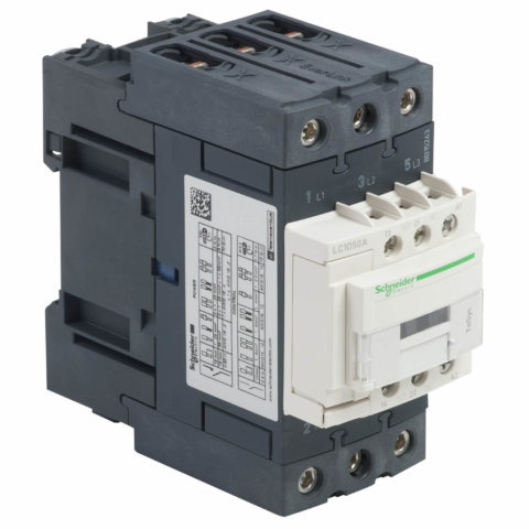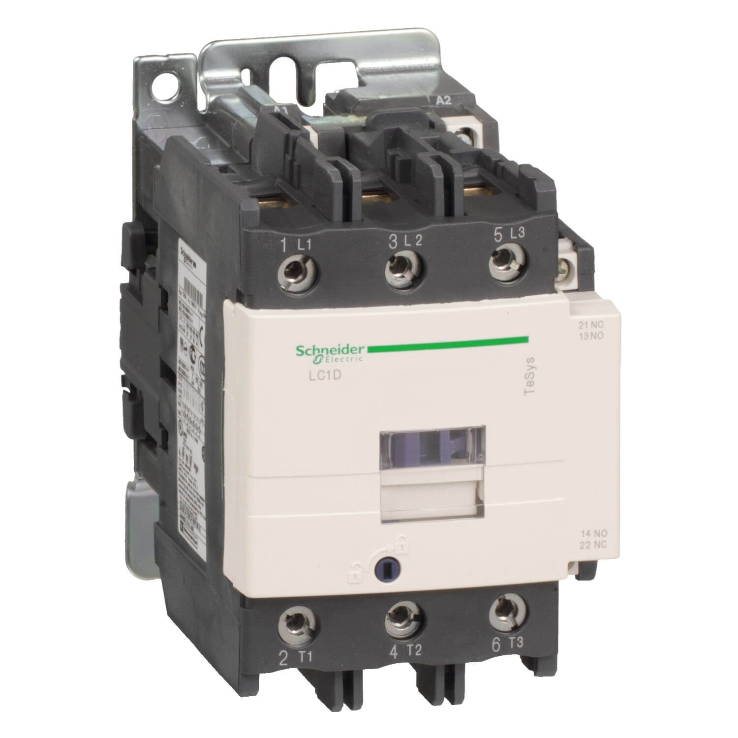
LC1D95B7 TeSys D contactor – 3P(3 NO) – AC-3 – <= 440 V 95 A – 24 V AC 50/60 Hz coil
Specification:
Main range TeSysproduct name TeSys Dproduct or component type Contactordevice short name LC1Dcontactor application Motor control
Resistive loadutilisation category AC-3
AC-4
AC-1poles description 3Ppower pole contact composition 3 NO[Ue] rated operational voltage Power circuit: 1000 V AC 25…400 Hz[Ie] rated operational current 95 A (at <60 °C) at <= 440 V AC-3 for power circuit
125 A (at <60 °C) at <= 690 V AC-1 for power circuitmotor power kW 25 kW at 220…230 V AC 50 Hz (AC-3)
45 kW at 380…400 V AC 50 Hz (AC-3)
45 kW at 415…440 V AC 50 Hz (AC-3)
55 kW at 500 V AC 50 Hz (AC-3)
45 kW at 660…690 V AC 50 Hz (AC-3)
45 kW at 1000 V AC 50 Hz (AC-3)motor power HP (UL / CSA) 7.5 hp at 115 V AC 60 Hz for 1 phase motors
15 hp at 230/240 V AC 60 Hz for 1 phase motors
25 hp at 200/208 V AC 60 Hz for 3 phases motors
30 hp at 230/240 V AC 60 Hz for 3 phases motors
60 hp at 460/480 V AC 60 Hz for 3 phases motors
60 hp at 575/600 V AC 60 Hz for 3 phases motorscontrol circuit type AC at 50/60 Hz[Uc] control circuit voltage 24 V AC 50/60 Hzauxiliary contact composition 1 NO + 1 NC[Uimp] rated impulse withstand voltage 8 kV conforming to IEC 60947overvoltage category III[Ith] conventional free air thermal current 10 A (at 60 °C) for signalling circuit
125 A (at 60 °C) for power circuitIrms rated making capacity 1100 A at 440 V AC for power circuit conforming to IEC 60947
140 A AC for signalling circuit conforming to IEC 60947-5-1
250 A DC for signalling circuit conforming to IEC 60947-5-1rated breaking capacity 1100 A at 440 V for power circuit conforming to IEC 60947[Icw] rated short-time withstand current 1100 A 40 °C – 1 s for power circuit
800 A 40 °C – 10 s for power circuit
400 A 40 °C – 1 min for power circuit
135 A 40 °C – 10 min for power circuit
140 A – 100 ms for signalling circuit
120 A – 500 ms for signalling circuit
100 A – 1 s for signalling circuitassociated fuse rating 10 A gG for signalling circuit conforming to IEC 60947-5-1
200 A gG at <= 690 V coordination type 1 for power circuit
160 A gG at <= 690 V coordination type 2 for power circuitaverage impedance 0.8 mOhm – Ith 125 A 50 Hz for power circuit[Ui] rated insulation voltage Power circuit: 1000 V conforming to IEC 60947-4-1
Power circuit: 600 V CSA certified
Power circuit: 600 V UL certified
Signalling circuit: 690 V conforming to IEC 60947-1
Signalling circuit: 600 V CSA certified
Signalling circuit: 600 V UL certifiedelectrical durability 1.2 Mcycles 95 A AC-3
1.3 Mcycles 125 A AC-1power dissipation per pole 12.5 W AC-1
7.2 W AC-3Front cover Withmounting support Plate
Railstandards EN/IEC 60947-1
EN/IEC 60947-4-1
EN/IEC 60947-5-1
UL 60947-4-1
UL 60947-5-1
CSA C22.2 No 60947-4-1
CSA C22.2 No 60947-5-1
GB/T 14048.4product certifications IECEE CB Scheme
UL
CSA
CCC
EAC
LROS (Lloyds register of shipping)
RINA
BV
DNV-GLconnections – terminals Control circuit: screw clamp terminals 2 cable(s) 1…2.5 mm²flexible with cable end
Control circuit: screw clamp terminals 1 cable(s) 1…2.5 mm²flexible with cable end
Control circuit: screw clamp terminals 1 cable(s) 1…4 mm²flexible without cable end
Control circuit: screw clamp terminals 2 cable(s) 1…4 mm²flexible without cable end
Control circuit: screw clamp terminals 1 cable(s) 1…4 mm²solid without cable end
Control circuit: screw clamp terminals 2 cable(s) 1…4 mm²solid without cable end
Power circuit: connector 1 cable(s) 4…50 mm²flexible without cable end
Power circuit: connector 2 cable(s) 4…25 mm²flexible without cable end
Power circuit: connector 1 cable(s) 4…50 mm²flexible with cable end
Power circuit: connector 2 cable(s) 4…16 mm²flexible with cable end
Power circuit: connector 1 cable(s) 4…50 mm²solid without cable end
Power circuit: connector 2 cable(s) 4…25 mm²solid without cable endtightening torque Control circuit: 1.2 N.m – on screw clamp terminals – with screwdriver flat Ø 6 mm
Control circuit: 1.2 N.m – on screw clamp terminals – with screwdriver Philips No 2
Power circuit: 12 N.m – on connector – with screwdriver flat Ø 6 to Ø 8 mm
Power circuit: 12 N.m – on connector hexagonal screw head 4 mmoperating time 20…35 ms closing
6…20 ms openingsafety reliability level B10d = 1.3 Mcycles contactor with nominal load conforming to EN/ISO 13849-1
B10d = 20 Mcycles contactor with mechanical load conforming to EN/ISO 13849-1mechanical durability 4 Mcyclesmaximum operating rate 3600 cyc/h 60 °CComplementary coil technology Without built-in suppressor modulecontrol circuit voltage limits 0.8…1.1 Uc (-40…55 °C):operational AC 50 Hz
0.85…1.1 Uc (-40…55 °C):operational AC 60 Hz
0.3…0.6 Uc (-40…70 °C):drop-out AC 50/60 Hz
1…1.1 Uc (55…70 °C):operational AC 50/60 Hzinrush power in VA 245 VA 60 Hz cos phi 0.75 (at 20 °C)
245 VA 50 Hz cos phi 0.75 (at 20 °C)hold-in power consumption in VA 26 VA 60 Hz cos phi 0.3 (at 20 °C)
26 VA 50 Hz cos phi 0.3 (at 20 °C)heat dissipation 6…10 W at 50/60 Hzauxiliary contacts type type mechanically linked 1 NO + 1 NC conforming to IEC 60947-5-1
type mirror contact 1 NC conforming to IEC 60947-4-1signalling circuit frequency 25…400 Hzminimum switching current 5 mA for signalling circuitminimum switching voltage 17 V for signalling circuitnon-overlap time 1.5 ms on de-energisation between NC and NO contact
1.5 ms on energisation between NC and NO contactinsulation resistance > 10 MOhm for signalling circuitcontact compatibility M11compatibility code LC1Dmotor power range 55…100 kW at 480…500 V 3 phases
15…25 kW at 200…240 V 3 phases
30…50 kW at 380…440 V 3 phases
30…50 kW at 480…500 V 3 phasesmotor starter type Direct on-line contactorcontactor coil voltage 24 V AC standardEnvironment IP degree of protection IP20 front face conforming to IEC 60529protective treatment TH conforming to IEC 60068-2-30pollution degree 3ambient air temperature for operation -40…60 °C
60…70 °C with deratingambient air temperature for storage -60…80 °Coperating altitude 0…3000 mfire resistance 850 °C conforming to IEC 60695-2-1flame retardance V1 conforming to UL 94mechanical robustness Vibrations contactor open: 2 Gn, 5…300 Hz
Shocks contactor open: 8 Gn for 11 ms
Vibrations contactor closed: 3 Gn, 5…300 Hz
Shocks contactor closed: 10 Gn for 11 msheight 127 mmwidth 85 mmdepth 130 mmnet weight 1.61 kg