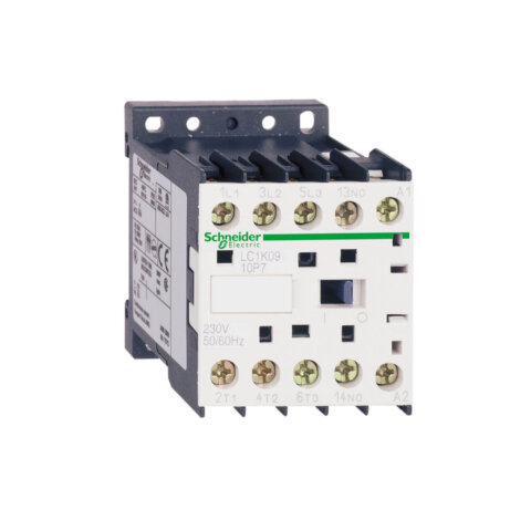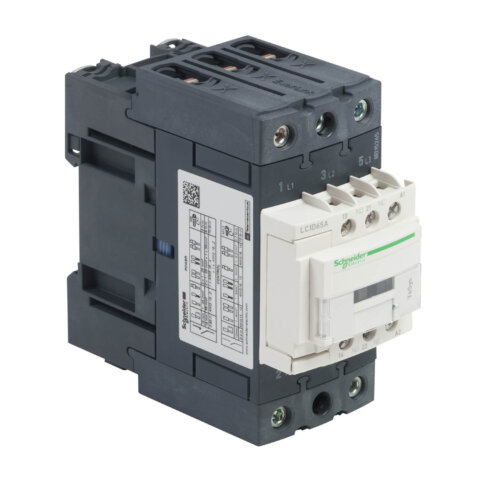
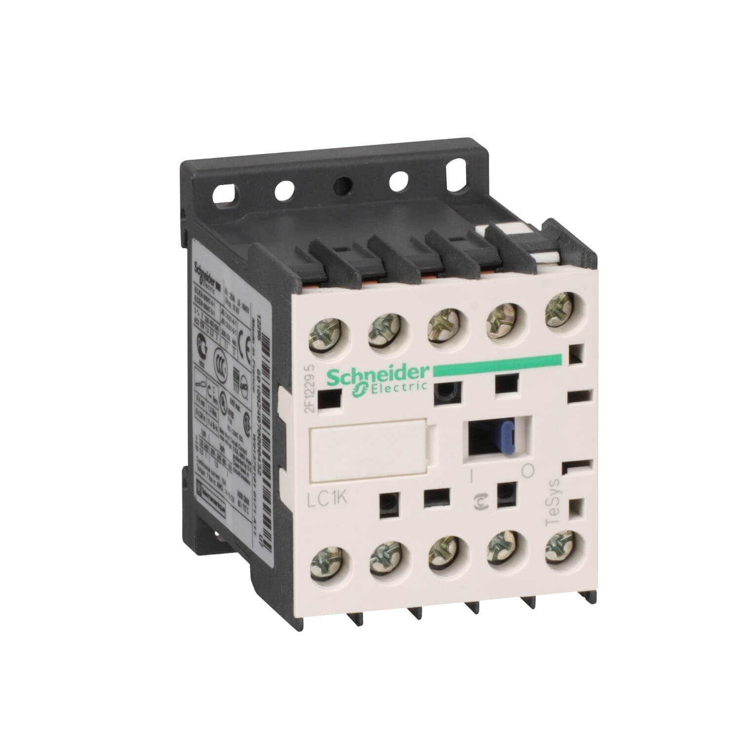
LC1K1210B7 TeSys K contactor – 3P – AC-3 <= 440 V 12 A – 1 NO aux. – 24 V AC coil
Specification:
| range | TeSys | |
|---|---|---|
| product or component type | Contactor | |
| product name | TeSys K | |
| device short name | LC1K | |
| device application | Control | |
| contactor application | Motor control Resistive load |
| utilisation category | AC-1 AC-4 AC-3 | |
|---|---|---|
| poles description | 3P | |
| power pole contact composition | 3 NO | |
| [Ue] rated operational voltage | Power circuit: 690 V AC 50/60 Hz Signalling circuit: <= 690 V AC 50/60 Hz | |
| [Ie] rated operational current | 20 A (at <50 °C) at <= 440 V AC AC-1 for power circuit 12 A at <= 440 V AC AC-3 for power circuit 16 A (at <70 °C) at 690 V AC AC-1 for power circuit | |
| control circuit type | AC at 50/60 Hz | |
| [Uc] control circuit voltage | 24 V AC 50/60 Hz | |
| motor power kW | 4 kW at 480 V AC 50/60 Hz AC-3 4 kW at 500…600 V AC 50/60 Hz AC-3 4 kW at 660…690 V AC 50/60 Hz AC-3 2.2 kW at 400 V AC 50/60 Hz AC-4 3 kW at 220…230 V AC 50/60 Hz AC-3 5.5 kW at 380…415 V AC 50/60 Hz AC-3 5.5 kW at 440 V AC 50/60 Hz AC-3 | |
| auxiliary contact composition | 1 NO | |
| [Uimp] rated impulse withstand voltage | 8 kV | |
| overvoltage category | III | |
| [Ith] conventional free air thermal current | 20 A (at 50 °C) for power circuit 10 A (at 50 °C) for signalling circuit | |
| Irms rated making capacity | 110 A AC for signalling circuit conforming to IEC 60947 144 A AC for power circuit conforming to NF C 63-110 144 A AC for power circuit conforming to IEC 60947 | |
| rated breaking capacity | 110 A at 440 V conforming to IEC 60947 80 A at 500 V conforming to IEC 60947 70 A at 660…690 V conforming to IEC 60947 | |
| [Icw] rated short-time withstand current | 115 A 50 °C – 1 s for power circuit 105 A 50 °C – 5 s for power circuit 100 A 50 °C – 10 s for power circuit 75 A 50 °C – 30 s for power circuit 55 A 50 °C – 1 min for power circuit 50 A 50 °C – 3 min for power circuit 80 A – 1 s for signalling circuit 90 A – 500 ms for signalling circuit 110 A – 100 ms for signalling circuit 25 A 50 °C – >= 15 min for power circuit | |
| associated fuse rating | 25 A gG at <= 440 V for power circuit 25 A aM for power circuit 10 A gG for signalling circuit conforming to IEC 60947 10 A gG for signalling circuit conforming to VDE 0660 | |
| average impedance | 3 mOhm – Ith 20 A 50 Hz for power circuit | |
| [Ui] rated insulation voltage | Power circuit: 600 V conforming to UL 508 Power circuit: 690 V conforming to IEC 60947-4-1 Signalling circuit: 690 V conforming to IEC 60947-4-1 Signalling circuit: 690 V conforming to IEC 60947-5-1 Signalling circuit: 600 V conforming to UL 508 Power circuit: 600 V conforming to CSA C22.2 No 14 Signalling circuit: 600 V conforming to CSA C22.2 No 14 | |
| insulation resistance | > 10 MOhm for signalling circuit | |
| inrush power in VA | 30 VA (at 20 °C) | |
| hold-in power consumption in VA | 4.5 VA (at 20 °C) | |
| heat dissipation | 1.3 W | |
| control circuit voltage limits | Operational: 0.8…1.15 Uc (at <50 °C) Drop-out: 0.2…0.75 Uc (at <50 °C) | |
| connections – terminals | Screw clamp terminals 2 cable(s) 4 mm²solid Screw clamp terminals 2 cable(s) 4 mm²flexible without cable end Screw clamp terminals 2 cable(s) 1.5 mm²flexible with cable end | |
| maximum operating rate | 3600 cyc/h | |
| auxiliary contacts type | type instantaneous 1 NO | |
| signalling circuit frequency | <= 400 Hz | |
| minimum switching current | 5 mA for signalling circuit | |
| minimum switching voltage | 17 V for signalling circuit | |
| mounting support | Plate Rail | |
| tightening torque | 1.3 N.m – on screw clamp terminals – with screwdriver Philips No 2 1.3 N.m – on screw clamp terminals – with screwdriver flat Ø 6 mm | |
| operating time | 10…20 ms coil de-energisation and NO opening 10…20 ms coil energisation and NO closing | |
| safety reliability level | B10d = 1369863 cycles contactor with nominal load conforming to EN/ISO 13849-1 B10d = 20000000 cycles contactor with mechanical load conforming to EN/ISO 13849-1 | |
| non overlap distance | 0.5 mm | |
| mechanical durability | 10 Mcycles | |
| electrical durability | 0.3 Mcycles 20 A AC-1 at Ue <= 440 V 1.3 Mcycles 12 A AC-3 at Ue <= 440 V | |
| mechanical robustness | Shocks contactor closed, on X axis: 10 Gn for 11 ms conforming to IEC 60068-2-27 Shocks contactor closed, on Y axis: 15 Gn for 11 ms conforming to IEC 60068-2-27 Shocks contactor closed, on Z axis: 15 Gn for 11 ms conforming to IEC 60068-2-27 Shocks contactor opened, on X axis: 6 Gn for 11 ms conforming to IEC 60068-2-27 Shocks contactor opened, on Y axis: 10 Gn for 11 ms conforming to IEC 60068-2-27 Shocks contactor opened, on Z axis: 10 Gn for 11 ms conforming to IEC 60068-2-27 Vibrations contactor closed: 4 Gn, 5…300 Hz conforming to IEC 60068-2-6 Vibrations contactor opened: 2 Gn, 5…300 Hz conforming to IEC 60068-2-6 | |
| height | 58 mm | |
| width | 45 mm | |
| depth | 57 mm | |
| net weight | 0.18 kg |